The simple cable programmer was submitted by Sample Electronics.
They produce professional programmers too. This simple programmer you can make yourself within a 10 minutes. And only a few resistors are needed.
The operation is the same a for the STK200/300 programmer.
What you need is a DB25 centronics male connector, a flat cable and a connector that can be connected to the target MCU board.
The connections to make are as following:
DB25 pin |
Target MCU pin(AT89S8252) |
DT104 |
2, D0 |
MOSI, pin 6 |
J5, pin 4 |
4, D2 |
RESET, pin 9 |
J5, pin 8 |
5, D3 |
CLOCK, pin 8 |
J5, pin 6 |
11, BUSY |
MISO, pin 7 |
J5, pin 5 |
18-25,GND |
GROUND |
J5, pin 1 |
The MCU pin numbers are shown for an 8252!
Note that 18-25 means pins 18,19,20,21,22,23,24 and 25
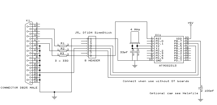
You can use a small resistor of 100 ohm in series with the D0, D2 and D3 line in order not to short circuit your LPT port in the event the MCU pins are high.
But it was tested without these resistors and my PC still works :-)
Tip : when testing programmers etc. on the LPT it is best to buy an I/O card for your PC that has a LPT port. This way you dont destroy your LPT port that is on the motherboard in the event you make a mistake!
The following picture shows the connections to make. Both a setup for the DT104 and stand alone PCB are shown.
I received the following useful information :
Hi Mark,
I have been having spurious success with the simple cable programmer from
Sample Electronics for the AVR series.
After resorting to hooking up the CRO I have figured it out (I think). When
trying to identify the chip, no response on the MISO pin indicates that the
Programming Enable command has not been correctly received by the target.
The SCK line Mark/Space times were okay but it looked a bit sad with a slow
rise time but a rapid fall time. So I initially tried to improve the rise
time with a pullup. No change ie still could not identify chip. I was about
to add some buffers when I came across an Atmel app note for their serial
programmer
"During this first phase of the programming cycle, keeping the SCK line
free from pulses is critical, as pulses will cause the target AVR to loose
syncronisation with the programmer. When syncronisation is lost, the only
means of regaining syncronisation is to release the RESET line for more
than 100ms."
I have added a 100pF cap from SCK to GND and works first time every time
now. The SCK rise time is still sad but there must have been enough noise
to corrupt the initial command despite using a 600mm shielded cable.
This may be useful to your users.
Regards,
Mark Hayne